Facebook

WELCOME TO OUR BLOG

We're sharing knowledgein the areas which fascinate us the most
click

Copeland ZB21KQE-TFD-558 Tough Conditions Guide: Discharge Temp Control, DTC Application & Liquid Protection

By Qishanr Compressors November 5th, 2026 2 views
Copeland ZB21KQE-TFD-558 Tough Conditions Guide: Discharge Temp Control, DTC Application & Liquid Protection

1. Introduction: Key Severe Operating Challenges in Medium-Temperature Commercial Refrigeration

In commercial cold storage and refrigeration engineering, the Copeland Scroll ZB21KQE-TFD-558 (a 3HP-class medium/high-temperature scroll compressor) is widely utilized in 0∘C∼+5∘C fresh food cold rooms, pre-cooling facilities, and supermarket medium-temperature display cases.

However, in actual field operation, systems frequently encounter various demanding operating conditions:
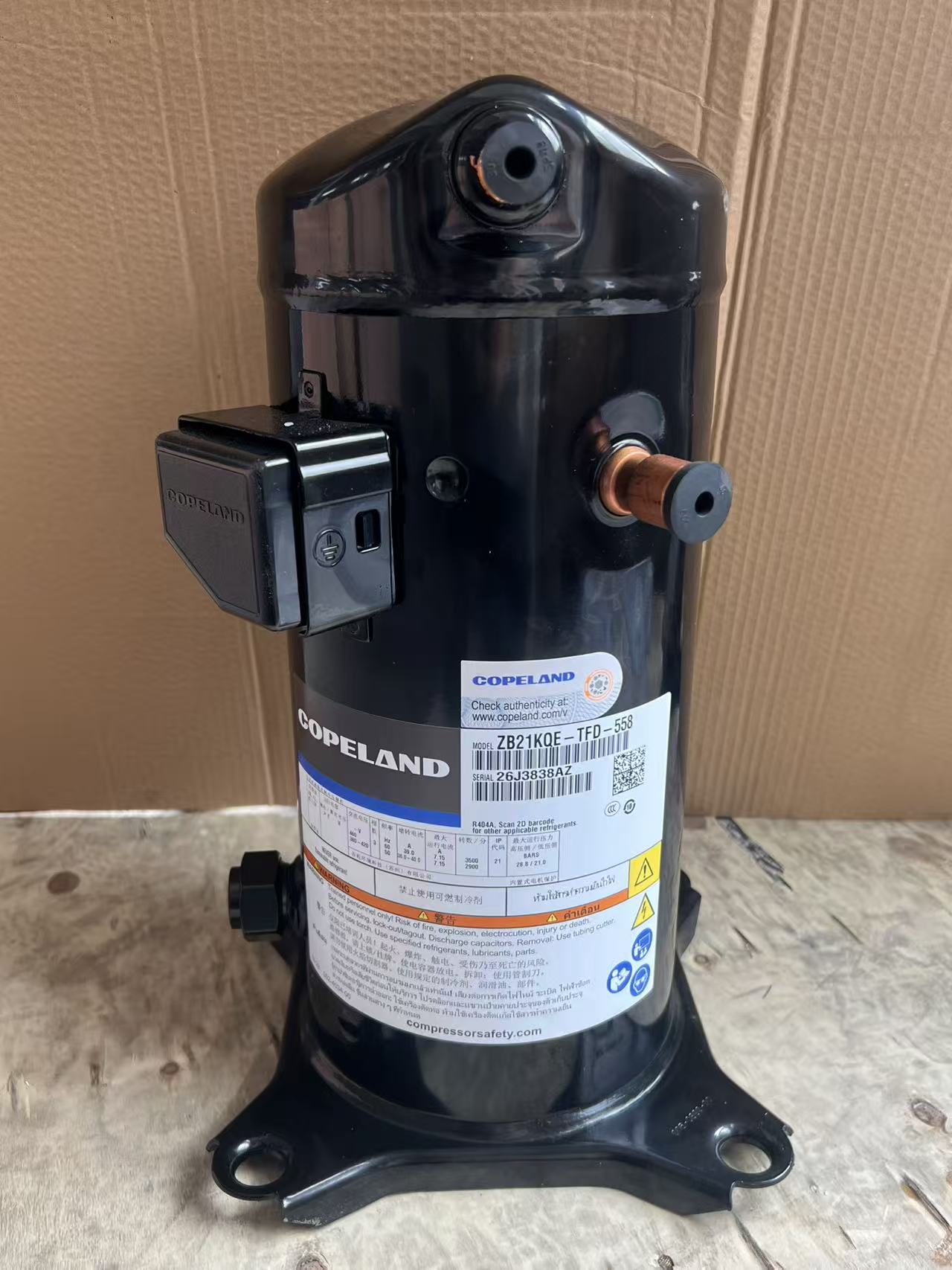
  1. High Summer Ambient & Limited Condenser Heat Dissipation: High outdoor ambient temperatures can drive condensing temperature Tc to elevated levels, forcing the compressor into high condensing pressure zones.
  2. Wide Pull-Down Temperature Spans & Defrost Cycling: Thermal loads accumulated in the evaporator during defrost can enter the suction line rapidly upon restart, creating high suction superheat alongside high pressure ratios.
  3. Liquid Floodback During Load Fluctuations: Slow thermal expansion valve response or inadequate suction separation can lead to unevaporated liquid refrigerant entering the compression chamber.


This guide examines the operational risks and system protection strategies for the ZB21KQE-TFD-558 across these conditions, focusing on thermodynamic operating limits and mechanical structural characteristics.


2. High Discharge Temperatures: Thermal Impact Mechanisms & Operating Limits

In medium-temperature refrigeration systems, sustained high discharge temperature (Discharge Temperature Overheat) is a primary contributor to accelerated wear and reduced compressor service life.

   ┌────────────────────────────────────────────────────────┐
   │ Severe Operating Factors: High Pressure Ratio          │
   │                           High Suction Superheat       │
   └───────────────────────────┬────────────────────────────┘
                               │
                               ▼
   ┌────────────────────────────────────────────────────────┐
   │ Rising Discharge Temperature (T_discharge > 130°C/266°F)│
   └───────────────────────────┬────────────────────────────┘
                               │
                               ▼
   ┌────────────────────────────────────────────────────────┐
   │ Lubrication Degradation Process:                       │
   │ 1. Accelerated thermal aging of POE oil in hot zones   │
   │ 2. Reduced oil viscosity ──► Compromised scroll film   │
   │ 3. Wear debris accumulation ──► Affects bearing life   │
   └───────────────────────────┘

2.1 Recommended Temperature Operating Limits

  • Discharge Line Guidelines: It is generally recommended that the discharge line temperature measured 150 mm from the discharge fitting remain below 120∘C (248∘F). The transient core temperature at the center of the scroll discharge port should avoid sustained operation above 135∘C.
  • Lubricating Oil Stability: Under prolonged high-temperature and high-pressure conditions, the chemical stability of the pre-charged POE synthetic ester oil in the ZB21KQE-TFD-558 can degrade, leading to reduced oil film strength and elevated mechanical wear risks.

2.2 Thermodynamic Analysis & Pressure Ratio Influence

Scroll compression is generally modeled as a polytropic compression process. The discharge temperature T2 depends primarily on the suction temperature T1 and the absolute compression ratio P2P1:

T2=T1⋅(P2P1)k−1k

When operating at lower evaporating temperatures (such as during pull-down with Te=−18∘C) combined with higher condensing temperatures (such as Tc≥+50∘C), the compression ratio P2P1 increases substantially. If suction superheat is excessive under these conditions, T2 can readily exceed safe design limits.


3. DTC Liquid Injection Cooling System: Working Principle & Piping Configuration

For extended medium-to-low temperature applications or elevated pressure ratios, the DTC (Discharge Temperature Control) Valve serves as a proven auxiliary cooling solution to regulate discharge temperatures on the ZB21KQE-TFD-558.

              ┌──────────────────────────────────────────────────┐
              │          Copeland ZB21KQE-TFD-558 Scroll         │
              │                                                  │
              │   ┌───────────────┐        ┌─────────────────┐   │
              │   │  Suction (S)  │        │  Discharge (D)  │   │
              └───┴───────▲───────┴────────┴────────┬────────┴───┘
                          │                         │
                          │   Thermal Bulb on Pipe  │ (≤150mm Sensing Point)
                          │   (Bulb Response)       ▼
                          │ ┌───────────────────┐ Discharge to Condenser
                          │ │ DTC Thermal Unit  │
                          │ └─────────┬─────────┘
                          │           │ Valve Opens (at Trigger Temp)
                          │           ▼
                          │   ┌───────────────┐
                          └───┤   DTC Valve   │ ◄─── Subcooled liquid from
                              └───────────────┘      receiver/filter drier

3.1 DTC Dynamic Modulation Process

  • Thermal Feedback: The DTC valve uses a dedicated sensing bulb secured directly to the bare copper discharge line within 150 mm of the discharge port and protected with thermal insulation.
  • Throttling & Cooling: When discharge temperatures reach the actuation threshold (typically around 105∘C±3∘C), the valve opens to inject a metered flow of subcooled liquid refrigerant into the suction side or dedicated injection port.
  • Latent Heat Vaporization: The injected liquid mist evaporates during the early stages of compression, absorbing compression heat and moderating temperature rise to keep discharge temperatures within safe operating limits (generally around 110∘C).

3.2 DTC Installation Guidelines

  1. Bulb Orientation: Mount the sensing bulb at the 2 o'clock or 10 o'clock position on horizontal discharge runs. Avoid bottom mounting to prevent pooled oil from slowing thermal response.
  2. Liquid Feed Sourcing: Draw liquid supply from the main liquid line downstream of the condenser/receiver and pass it through a liquid-line filter drier to ensure clean, single-phase liquid enters the DTC valve.

4. Liquid Handling & Floodback: Dual-Compliance Mechanism Tolerance

During defrost transitions, delayed expansion valve response, or severe evaporator frosting, mixed vapor-liquid refrigerant can enter the compressor suction (liquid floodback).

4.1 Mechanical Response to Liquid Ingestion

Mechanism Type Dynamic Response to Liquid Ingestion Typical Failure Mode
Traditional Reciprocating Piston attempts to compress non-compressible fluid; internal cylinder pressure spikes abruptly Valve reed fracture, piston crown damage, bent or broken connecting rods
Copeland ZB21KQE-TFD-558 Radial Compliance: Orbiting scroll yields laterally under resistance
Axial Compliance: Fixed scroll lifts slightly to relieve intermediate pressure
Liquid passes through the compression pockets and scrolls reseat, significantly reducing mechanical damage risks
[Radial & Axial Dual Compliance Relief Mechanism]

         Fixed Scroll
     ┌────────────────────────────┐  ▲ Axial Relief Gap
     │   ┌──┐              ┌──┐   │  │ (Fixed scroll lifts slightly under excessive
     │   │  │  Compression │  │   │  │  pressure to vent trapped liquid upward)
     └───┴──┼────Pocket────┼──┴───┘
            │ Liquid/Debris│
     ┌───┬──┼──────────────┼──┬───┐
     │   │  │   (Liquid)   │  │   │  ◄── Radial Relief Clearance
     │   └──┘              └──┘   │      (Eccentric drive allows orbiting scroll to
     └────────────────────────────┘       shift radially, separating flank contacts)
        Orbiting Scroll

4.2 Standstill Refrigerant Migration & Pre-Start Heating

While the dual-compliance design provides strong tolerance to transient liquid intake during operation, refrigerant migration into the oil during extended off-cycles requires careful management:

  • Migration & Dissolution: During off-cycles in cold environments, refrigerant vapor naturally migrates to the colder crankcase and dissolves into the POE lubricant.
  • Start-Up Foaming: At compressor startup, the sudden drop in crankcase pressure causes dissolved refrigerant to boil vigorously, generating oil foam that can momentarily interrupt oil delivery to the bearings and increase oil carryover into the system.
  • Recommended Protection: Install a crankcase heater around the lower compressor shell. Energize the heater for 8–12 hours prior to initial commissioning or after extended power shutdowns to maintain oil temperature safely above the ambient dew point before startup.

5. Electrical & Thermal Overload Protection: TFD Electrical Architecture

The electrical code TFD designates a 380–420V/3Ph/50Hz (or 460V/3Ph/60Hz) motor with internal thermal protection features.

5.1 Internal Motor Protector

  • Sensing Configuration: The internal thermal protector is embedded at the neutral star point of the three-phase stator windings.
  • Operating Logic: The device monitors both winding temperature and operating current. Under prolonged severe overload or locked-rotor conditions, the protector opens the star center to disconnect all three phases.
  • Reset Characteristics: The protector uses an automatic thermal reset design. It will reclose only after the motor windings have cooled to a safe range. Bypassing or forcing contactors closed before finding the root cause is not recommended.

5.2 Rotational Direction & Phase Sequence Management

  • Unidirectional Operation: Scroll compressors are designed to rotate in one specific direction. If three-phase power is connected with reversed phase sequence, the scroll operates in reverse.
  • Symptoms of Reverse Rotation:
    1. Failure to establish normal suction and discharge pressure differentials (pressures remain nearly equal).
    2. Noticeable operational sound differences compared to normal running conditions.
    3. Rapid motor temperature rise due to the absence of continuous suction gas cooling, leading to internal thermal protector tripping.
  • Engineering Recommendation: Integrate a three-phase phase sequence monitoring relay into the electrical control panel to prevent reverse rotation caused by utility changes or wiring errors.

Conclusion

With its proprietary axial and radial dual-compliance design, the Copeland ZB21KQE-TFD-558 delivers reliable mechanical robustness and transient liquid tolerance in medium-temperature commercial refrigeration applications. When pairing this unit with DTC liquid injection, proper crankcase preheating, and phase sequence protection, engineers can effectively mitigate overheating and lubrication risks to ensure stable, long-term system performance.

Sizing the Sweet Spot: Why the Copeland ZP61KCE-TF7-522 Remains a Strategic Staple in Commercial HVAC & Heat Pumps
Previous
Sizing the Sweet Spot: Why the Copeland ZP61KCE-TF7-522 Remains a Strategic Staple in Commercial HVAC & Heat Pumps
Read More
3× Copeland ZB38KQE-TFD-558 Parallel Rack (15HP) Engineering Guide: Crankcase Differential Pressure Management and 45° Suction Header Oil Balancing
Next
3× Copeland ZB38KQE-TFD-558 Parallel Rack (15HP) Engineering Guide: Crankcase Differential Pressure Management and 45° Suction Header Oil Balancing
Read More
Leave a message
Name
E-mail *
Message
WhatsApp/WeChat
Country/Region
CONTACT US *
Click to verify