Facebook

WELCOME TO OUR BLOG

We're sharing knowledgein the areas which fascinate us the most
click

3× Copeland ZB38KQE-TFD-558 Parallel Rack (15HP) Engineering Guide: Crankcase Differential Pressure Management and 45° Suction Header Oil Balancing

By Qishanr Compressors November 5th, 2026 2 views
3× Copeland ZB38KQE-TFD-558 Parallel Rack (15HP) Engineering Guide: Crankcase Differential Pressure Management and 45° Suction Header Oil Balancing

1. System Architecture: 3× ZB38KQE-TFD-558 Parallel Rack vs. Single 15HP Compressor

In commercial medium-temperature cold storage (0∘C to +5∘C), pre-cooling facilities (−5∘C to −10∘C), and industrial process cooling, engineering teams frequently evaluate between a single 15HP compressor and a parallel rack comprising three 5HP Copeland ZB38KQE-TFD-558 scroll compressors.
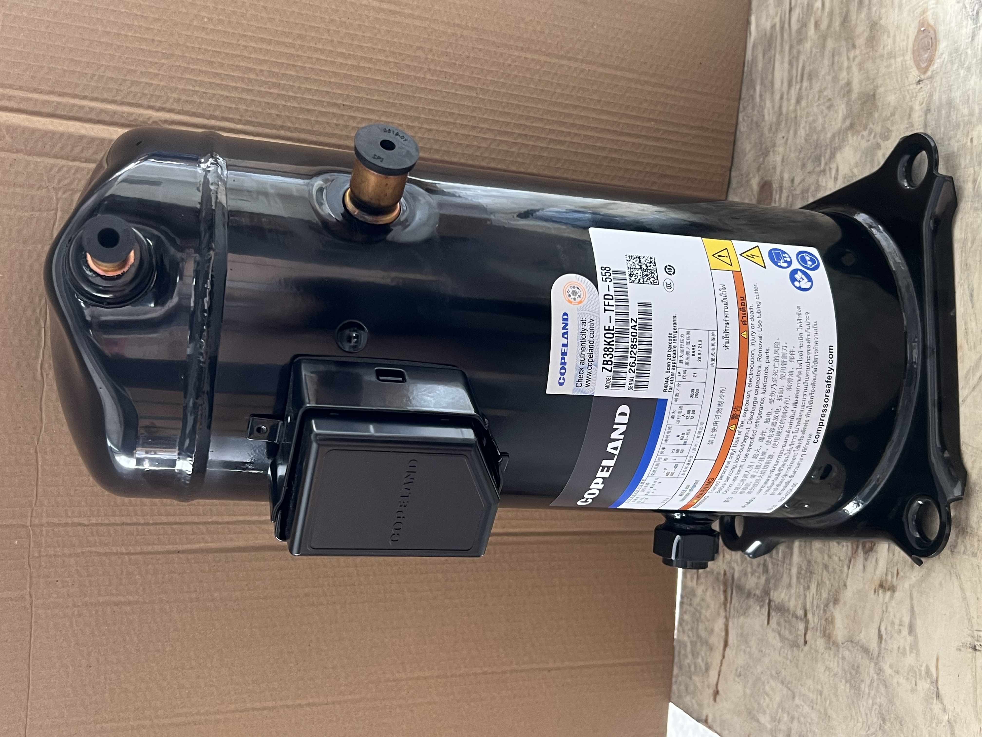
A comparative technical assessment highlights the distinct operational characteristics of both approaches:

Evaluation Metric Single 15HP Compressor 3× ZB38KQE-TFD-558 Parallel Rack Practical Engineering Impact
Capacity Modulation On/Off cycling or mechanical unloader / VFD control 33% - 66% - 100% 3-stage stepped modulation Better accommodates diurnal load shifts, reducing mechanical wear and thermal cycling from frequent on/off events.
Grid Starting Inrush High locked rotor current (typically LRA >140A) Staggered timed startup (Single unit LRA: 58.6∼65.5A) Moderates inrush current demand on local distribution transformers, easing breaker and contactor sizing.
System Redundancy Single point of failure halts all cooling output Single unit failure retains ~66% baseline capacity Facilitates online maintenance and protects stored perishable inventory from rapid temperature rise.
Displacement & Capacity Displacement approx. 43∼45 m3/h 14.4 m3/h×3=43.2 m3/h Yields a nominal cooling capacity of ≈24.8 kW (R404A @ Te=−5∘C,Tc=+45∘C).

2. Fluid Dynamics: 45° Suction Header Take-off and Oil Distribution

In multi-scroll parallel configurations, piping geometry plays a decisive role in ensuring balanced vapor-oil distribution during active operation while reducing oil migration into idle compressors.

2.1 Velocity Guidelines and Sizing

  • Horizontal Header Sections: Maintain vapor velocity between 4.0 and 6.0 m/s, pitched downward toward the accumulator/compressors at approximately 0.5%∼1%.
  • Vertical Suction Risers: Maintain velocity between 7.0 and 12.0 m/s to sustain turbulent flow and provide sufficient kinetic energy for continuous POE oil lift.
              [Suction Main Header from Evaporator/Accumulator] (4~6 m/s, 1:100 slope)
             ═════════════════════════════════════════════════════════════════════════╗
                 ▲ 45° Top Take-Off          ▲ 45° Top Take-Off          ▲ 45° Top Take-Off
                 │ (Branch 1)                │ (Branch 2)                │ (Branch 3)
            ┌────┴────┐                 ┌────┴────┐                 ┌────┴────┐
            │Inverted │                 │Inverted │                 │Inverted │
            │  Trap   │                 │  Trap   │                 │  Trap   │
            └────┬────┘                 └────┬────┘                 └────┬────┘
                 ▼ 7/8" Suction Branch       ▼ 7/8" Suction Branch       ▼ 7/8" Suction Branch
            ┌─────────┐                 ┌─────────┐                 ┌─────────┐
            │ Comp #1 │                 │ Comp #2 │                 │ Comp #3 │
            │ ZB38KQE │                 │ ZB38KQE │                 │ ZB38KQE │
            └─────────┘                 └─────────┘                 └─────────┘

2.2 Mechanism of the 45° Top-Takeoff Branch

  • Non-Recommended Practice: Branching off directly from the bottom or horizontal centerline of the suction header. In this setup, refrigerant liquid and oil film settling at the header base drain directly into idle units by gravity, increasing floodback risk upon restart while starving active units of lubricant.
  • Recommended Practice: Take branches off at a 45∘ angle in the direction of gas flow from the top of the header, routed through an inverted trap before dropping down to the 7/8′′ brazed suction inlet of the ZB38KQE.

3. Crankcase Micro-Differential Pressure and Oil Equalization Strategies

Because scroll compressor suction chambers communicate directly with their motor compartments, internal flow fields are highly dynamic. In parallel operation, minor internal pressure variations (ΔP≥0.02 bar) can disrupt the oil balance across sumps.

3.1 Physics of Oil Level Imbalance

Derived from hydrostatic balance: Δh=ΔPρoil⋅g With POE lubricant density ρoil≈980 kg/m3, a modest gas pressure delta of 0.02 bar (2000 Pa) theoretically creates an oil column height difference of: Δh=2000980×9.81≈0.208 m(≈21 cm) Given the compact vertical height of the ZB38KQE-TFD-558 sight glass, this differential can siphon lubricant from higher-pressure sumps into lower-pressure units.

              [Compressor #1] (P1 = 3.52 bar)         [Compressor #2] (P2 = 3.50 bar)
           ┌──────────────────────────────────┐    ┌──────────────────────────────────┐
           │     Scroll Compression Chamber   │    │     Scroll Compression Chamber   │
           ├──────────────────────────────────┤    ├──────────────────────────────────┤
           │      Micro Pressure Delta        │    │          ΔP = 0.02 bar           │
           ├──────────────────────────────────┤    ├──────────────────────────────────┤
           │      Oil Level Siphoned Low      │    │     Oil Level Driven High        │
           │                                  │    │          ████████                │
           │            ██                    │    │          ████████                │
           └────────────▲─────────────────────┘    └──────────▲───────────────────────┘
                        │                                     │
                        └════════ Simple Interconnecting Pipe ┘
                                 (Limited Equalization)

3.2 Oil Equalization Methods

Method A: Dual Gas/Oil Equalization Lines (Typically limited to 2-unit racks)

  • Configuration: An interconnecting ϕ12 mm (1/2′′) oil line at sight-glass center height, paired with a ϕ16 mm (5/8′′) gas equalization line across the upper crankcases.
  • Suitability: Straightforward architecture, but sensitive to level mounting and piping balance; equalization effectiveness diminishes in 3-compressor or larger arrangements.

Method B: Active Electronic Oil Level Management (Recommended for 3× ZB38KQE Racks)

[3× ZB38KQE Discharge Lines] ──► [High-Efficiency Oil Separator]
                                              │
                                       (Separated Oil)
                                              ▼
                                   [Dedicated Oil Reservoir]
                                              │ (Diff Check Valve ΔP ≈ 1.4 bar)
                                              ▼
                 ┌────────────────────────────┼────────────────────────────┐
                 │                            │                            │
                 ▼                            ▼                            ▼
          [Electronic Oil              [Electronic Oil              [Electronic Oil
           Level Control #1]            Level Control #2]            Level Control #3]
          (Fitted to Sight Glass)      (Fitted to Sight Glass)      (Fitted to Sight Glass)
                 │                            │                            │
                 ▼                            ▼                            ▼
           [ZB38KQE #1]                 [ZB38KQE #2]                 [ZB38KQE #3]
        (Controlled 1/2 Level)       (Controlled 1/2 Level)       (Controlled 1/2 Level)
  • Operational Logic:
    1. High-efficiency centrifugal oil separator reclaims discharged oil into a central reservoir.
    2. Electronic oil level regulators (e.g., Emerson TraxOil EC3 / Castel OMB) thread directly into the BOM-558 sight glass ports.
    3. Optical/Hall-effect sensors monitor sump levels continuously, pulsing solenoid valves to inject oil when levels dip below 1/3, and outputting alarm/trip signals if recovery thresholds are exceeded.

4. Discharge Manifold and Reverse Flow Protection

4.1 Compressor Discharge Branch Design

  • Each unit's 1/2′′ discharge stub should include an independent spring-loaded high-temperature check valve and service ball valve to mitigate gas backflow and reverse rotation upon shutdown.
  • Branch connections should enter the top of the discharge header at a 45∘ angle with flow direction.

4.2 Inverted Discharge Trap

  • An inverted trap (minimum height 250 mm above condenser inlet level) should be installed where the common discharge header transitions toward the air-cooled condenser to impede condensed liquid refrigerant and migrated lubricant from draining back toward compressor discharge valves.

5. Electrical Staging and Control Automation

[Suction Pressure Transmitter]
               │
               ▼
   [PLC Multi-Stage PID Controller]
               │
     ┌─────────┼─────────┐
     ▼         ▼         ▼
[Low Load] [Mid Load] [High Load]
 1 Active   2 Active   3 Active (100%)
               │
               ▼
   [FIFO Runtime Rotation Algorithm]
   - Least-run unit starts first
   - Longest-run unit stages off first
   - Inter-stage start delay: ≥ 180 seconds (Limits grid inrush & stabilizes oil film)

5.1 Electrical Specifications & Protection Parameters

  • Rated Load Amps (RLA): 8.9 A per compressor (380V / 3Ph / 50Hz);
  • Locked Rotor Amps (LRA): 58.6∼65.5 A per compressor;
  • Circuit Protection: Independent 16A∼20A Type D motor circuit breakers per compressor;
  • Contactors: Rated for AC-3 inductive loads ≥18A;
  • Phase Sequence Monitoring: A dedicated 3-phase sequence monitoring relay should be interlocked with the control circuit to prevent reverse scroll rotation.

6. Engineering Summary & Key Takeaways

Employing three Copeland ZB38KQE-TFD-558 compressors in a 15HP parallel rack offers a well-balanced solution combining high volumetric efficiency, flexible capacity modulation, and built-in redundancy for commercial refrigeration applications. Successful implementation relies on three foundational engineering practices:

  1. Fluid-Directed Header Geometry: The use of 45∘ top-takeoff suction branches and inverted discharge traps provides a physical safeguard against liquid pooling and oil maldistribution.
  2. Active Oil Management: For three-compressor racks, utilizing the BOM-558 sight glass port with active electronic oil level regulators reliably addresses crankcase differential pressure issues.
  3. Equitable Runtime Automation: Implementing FIFO runtime balancing with adequate inter-stage start delays (≥180s) dampens electrical starting shocks and harmonizes component wear across all three units.
Copeland ZB21KQE-TFD-558 Tough Conditions Guide: Discharge Temp Control, DTC Application & Liquid Protection
Previous
Copeland ZB21KQE-TFD-558 Tough Conditions Guide: Discharge Temp Control, DTC Application & Liquid Protection
Read More
Leave a message
Name
E-mail *
Message
WhatsApp/WeChat
Country/Region
CONTACT US *
Click to verify